Sunday 30 September 2012

Source code for Wind Turbine Generator in Train System


***coding for charging circuit

#include <16F877a.h>  //use pic16f877a
#device adc=10  //use 10bit adc detect bat voltage
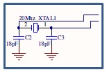
#use delay(clock=20000000) //clock speed=20mhz
#fuses hs,noprotect,nowdt  //default setting
#define use_portb_lcd TRUE //use portb for lcd
#include <lcd.c>  //call lcd.c library

//enable port a, b, c, d, e
#byte PORTA=5
#byte PORTB=6
#byte PORTC=7
#byte PORTD=8
#byte PORTE=9

long int adc1;
long int adc2;
int mycount=40;
float mybat, mywind;

void main()
{
   //initialize system
   set_tris_a(0b11111111);
   set_tris_b(0b00000000);
   set_tris_c(0b00000000);
   set_tris_d(0b00000000);
   set_tris_e(0b00000000);
   setup_port_a(ALL_ANALOG);
   setup_adc(ADC_CLOCK_INTERNAL);
   output_low(pin_d2);  //stop charging
  
   output_high(pin_d5); //on green led
   output_high(pin_d4); //on red led
   delay_ms(1000);
   output_low(pin_d5); //off green led
   output_low(pin_d4); //off red led

   lcd_init();
   lcd_putc("\f");

   do
   {
      if(mycount==40)
      {
         mycount=0;
     
         //cutoff charging
         output_low(pin_d2);
         delay_ms(200);

         //read solar volt
         set_adc_channel(0);
         delay_ms(10);
         adc1=read_adc();
         mywind=adc1/65.41;         
         delay_ms(10);

         //read  battery volt
         set_adc_channel(1);
         delay_ms(10);
         adc2=read_adc();
         mybat=adc2/65.41;        
         delay_ms(10);

         //display output
         printf(lcd_putc,"\fB:%.2f W:%.2f ",mybat, mywind);

         if(mybat<12)  //if battery < 12V
         {
            output_low(pin_d5); //off green led
            output_high(pin_d4); //on red led
            output_high(pin_d2);  //charge battery
            printf(lcd_putc,"\nBat Charging    ");
         }
         else   //if battery >= 12V
         {
            output_high(pin_d5); //on green led
            output_low(pin_d4); //off red led
            output_low(pin_d2);  //stop charge battery       
            printf(lcd_putc,"\nBat Not Charging");
         }
      }
      else
      {
         mycount=mycount+1;   //increase counter
      }
      delay_ms(250);
   }while(1);
}

Schematic diagram for Wind Turbine Generator in Train System


Schematic diagram 


Schematic diagram explainations


                   1)  20 MHz crystal

·       20 MHz crystal is  used in order to enable the PIC to execute every single program line in the system
·     20 MHz crystal is used because this is the maximum frequency that the PIC can support. If   the speed is less than 20 MHz then the PIC response speed will be slower.
·        If over frequency the PIC will burn.


                   2)  Voltage regulator LM7805

·        To protect PIC and other connected sensors / actuators from over voltage (maximum 5V).
·       It supports input voltage from 7V DC to 18V DC. If the input voltage is over, the LM7805 will burn or auto shutdown due to overheat.
·    The generated 5V from LM7805 will be noise filtered by 0.1uF ceramic capacitor and a 1000uF electrolytic capacitor. This is to avoid high frequency oscillation on the outputs which may cause system hang or unstable.
·   A diode is connected at the input of the LM7805. This is to avoid voltage connected reversely.
·       The power LED is used to indicate the system is ‘ON’/running.


                    3)  Relay (5V Relay-SPDT)

·   A relay is used to start or stop charging the operation. This relay is controlled by PIC microcontroller. Whenever the charging operation is running, a LED indicator will turn on else the LED indicator will turn off. 


                             4)   PIC16F877A microcontroller

·     PIC16F877A microcontroller is used to control the whole system.
·     Port A is used for input. The inputs are from battery and motor.
·     Port B is used for LCD display.
·     Port D is used for outputs. There are three LEDs used as indicators. The red LED at pin RD4 is used to show battery voltage less than 12V or not fully charge. The green LED at pin RD5 is to indicate when the battery is full while the green LED at pin RD2 is to show battery is charging.

5)  LCD display

·                                            ·  LCD display is used to show the wind generator and battery voltage.


                                             6)   Diode (lN 4007)

·    Diode is used to make sure current flows in one way. This is to prevent the current to go reverse and hence can damage the components.


Sunday 16 September 2012

Procedure for PCB design


Step 1

Step 2

Step 3

Step 4

Step 5

Step 6

Step 7

Step 8

Step 9

Step 10

Step 11

Step 12

Step 13

Step 14

Step 15


Sunday 9 September 2012

Charging circuit


The main circuit for this Wind Power Generator in Train System is charging circuit. The system is using wind generator to charge the 12VDC battery. A relay is used to start or stop charging. This relay is controlled by PIC microcontroller. Whenever the charging operation is running, a LED indicator will turn on else the LED indicator will turn off.

Two voltage dividers are being used to detect battery voltage and wind generator voltage. The voltage divider is used to avoid over voltage over 5V access PIC microcontroller. 


Below shows the calculation for the voltage divider:-
  •        When voltage input from wind generator or battery is 15.64V, PIC will get maximum voltage 5V.


Ratio = Voltage input from wind generator or battery / PIC voltage
Ratio = 15.64V/5V
Ratio = 3.128/1
So, the ratio is 3 to 1

Voltage divider formula:-
VDR = [R1 / (R1+R2)] x Vin

[4.7k / (4.7k + 10k)] x 5V = 1.599V
[10k / (10k + 4.7k)] x 5V = 3.401V
Total voltage = V1 + V2
Total voltage = 3.401V + 1.599V
Total voltage = 5V

3.401V x 3.128 = 1064V
1.599V x 3.128 = 5V
Total voltage = V1 + V2
Total voltage = 10.64V + 5V
Total voltage = 15.64V

So, input voltage must not exceeding 15.64V or else PIC will burn because PIC only supports 5V.