Schematic diagram

Schematic diagram explainations
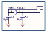
1) 20
MHz crystal
· 20 MHz crystal is used in order to enable the PIC to execute
every single program line in the system
· 20 MHz crystal is used because this is
the maximum frequency that the PIC
can support. If the speed is less than 20 MHz then the PIC response speed will
be slower.
· If over frequency the PIC will burn.

2) Voltage
regulator LM7805
· To protect PIC
and other connected sensors / actuators from over voltage (maximum 5V).
· It supports input voltage from 7V DC to
18V DC. If the input voltage is over, the LM7805 will burn or auto shutdown due
to overheat.
· The generated 5V from LM7805 will be
noise filtered by 0.1uF ceramic capacitor and a 1000uF electrolytic capacitor.
This is to avoid high frequency oscillation on the outputs which may cause
system hang or unstable.
· A diode is connected at the input of the
LM7805. This is to avoid voltage connected reversely.
· The power LED is used to indicate the
system is ‘ON’/running.

3) Relay
(5V Relay-SPDT)
· A relay is used to start or stop charging the operation. This relay is controlled by PIC microcontroller. Whenever the charging operation is
running, a LED indicator will turn on else the LED indicator will turn off.

4) PIC16F877A microcontroller
· PIC16F877A microcontroller is used to
control the whole system.
· Port A is used for input. The inputs are
from battery and motor.
· Port B is used for LCD display.
· Port D is used for outputs. There are
three LEDs used as indicators. The red LED at pin RD4 is used to show battery
voltage less than 12V or not fully charge. The green LED at pin RD5 is to
indicate when the battery is full while the green LED at pin RD2 is to show
battery is charging.
5) LCD display
· · LCD display is used to show the wind
generator and battery voltage.

6) Diode
(lN 4007)
· Diode is used to make sure current flows
in one way. This is to prevent the current to go reverse and hence can damage
the components.
Mohon maaf,,,mas Shahnizam...
ReplyDeletesaya meu tanya sedikit tentang software apa yang digunkan untuk membuat gambar skema diatas..?
apa bisa langsung bisa disimulasikan....mohon pencerahannya (alfian.ian3@gmail.com)